Electromechanical design · Completed
2.5-DOF Cartesian fishing game
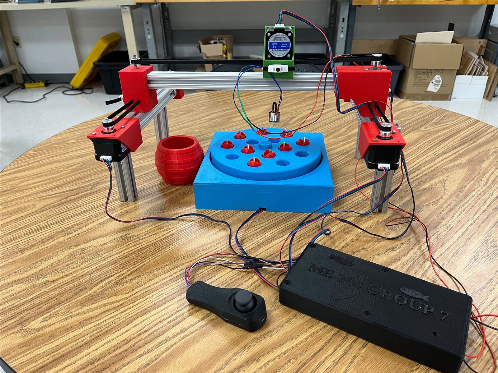
A completed joystick-controlled fishing game built around a belt-driven Cartesian gantry, motorized Z dip, electromagnet, and three-round rotating game board.
Boston University · ME360 · CAD lead · Fall 2026
On this page
- Role
- CAD lead
- Contribution
- CAD and mechanical layout; fabrication, controls, integration, and testing were team work.
- Evidence
- Classroom demonstration completed with X-Y-Z control, magnetic pickup, and all three game rounds working
Objective
The assignment required a 2.5-degree-of-freedom system with at least a 2.5 × 2.5 in end-effector work area. Our team turned that requirement into a tabletop fishing game: the player positions an electromagnet above a rotating board, lowers it to collect a piece, and moves the piece to the collection barrel.
The mechanism uses two synchronized X rails, one Y rail, and a limited motorized Z stroke. The earlier Cartesian plotter exercise established basic multi-axis motion before this belt-driven system was assembled.
CAD and system layout
I led the CAD and mechanical-layout work. The assembly model organized the aluminum-extrusion frame, belt paths, stepper-motor mounts, X and Y carriages, Z mechanism, rotating board, joystick housing, and electronics enclosure before final integration.
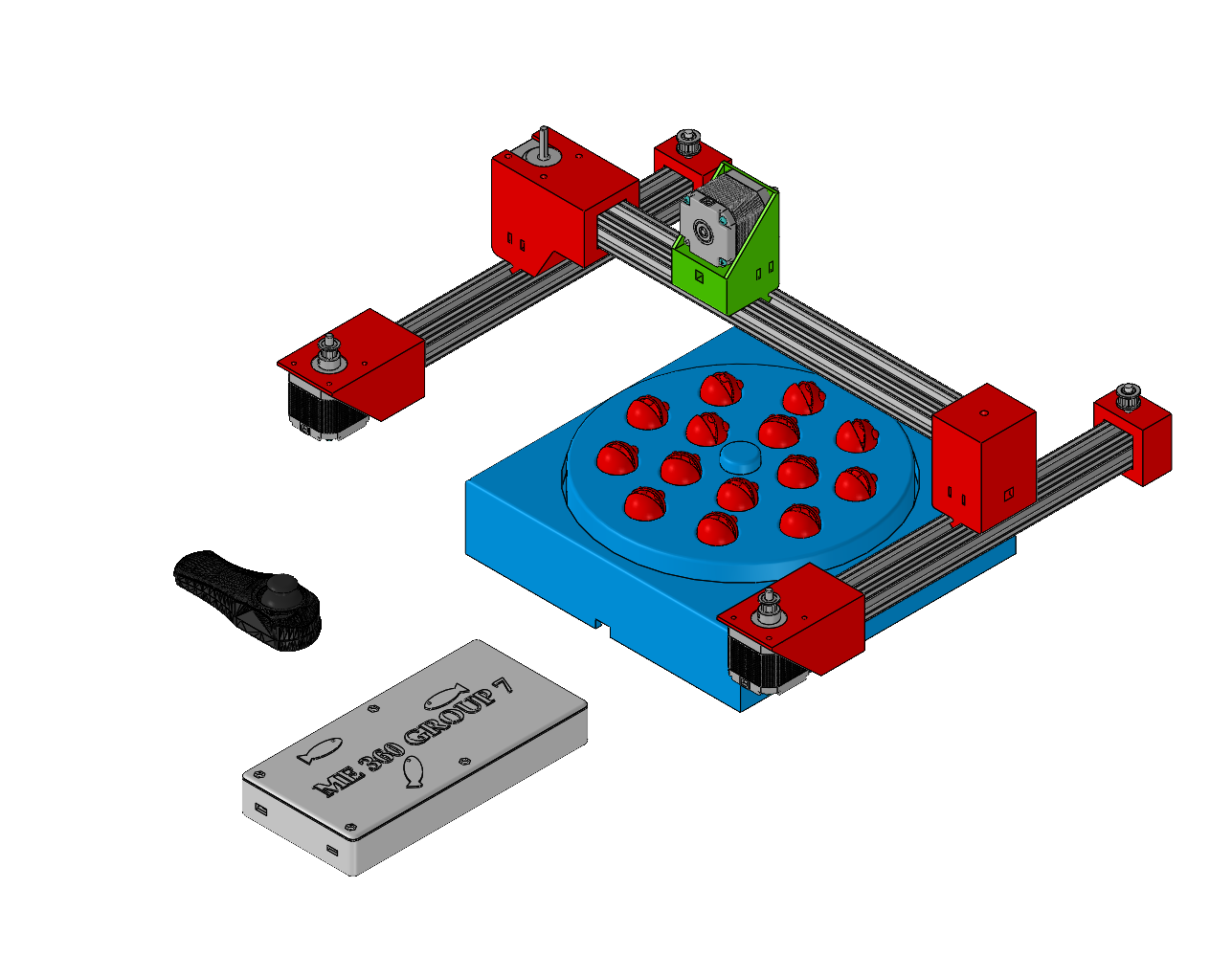
The paired X motors move both sides of the bridge together. A third belt stage moves the green Y carriage across the bridge. This layout keeps the work area open while supporting the Z motor and electromagnet above the game board.
Belt-driven linear stages
Each horizontal stage uses an 80/20 aluminum extrusion as both structure and linear guide. Stepper motors drive timing belts around toothed and idler pulleys. Custom printed housings locate the motors, pulleys, belt returns, and sliding interfaces; standard screws secure the housings to the extrusion.
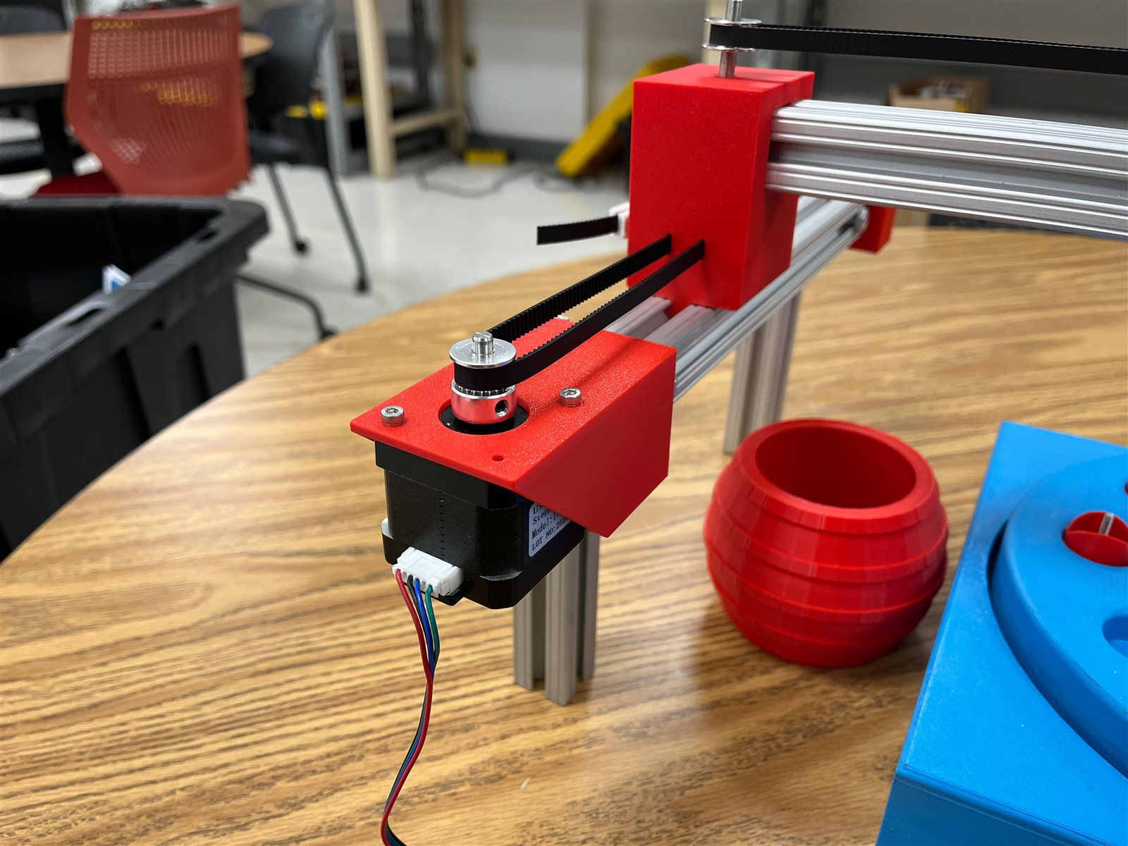
The final assembly uses two X rails so the crossbeam does not cant under the Y-axis and end-effector load. The two X motors receive synchronized step pulses from separate driver channels.
Z motion and magnetic pickup
The green carriage carries a fourth stepper motor for the constrained Z motion. A line suspended from its shaft lowers the electromagnet toward the board, pauses at the bottom of the stroke, and returns to the starting height. The controller locks X-Y commands during this sequence to keep the pickup point stable. The slow Z motion was a deliberate design choice for a controlled pickup and return.
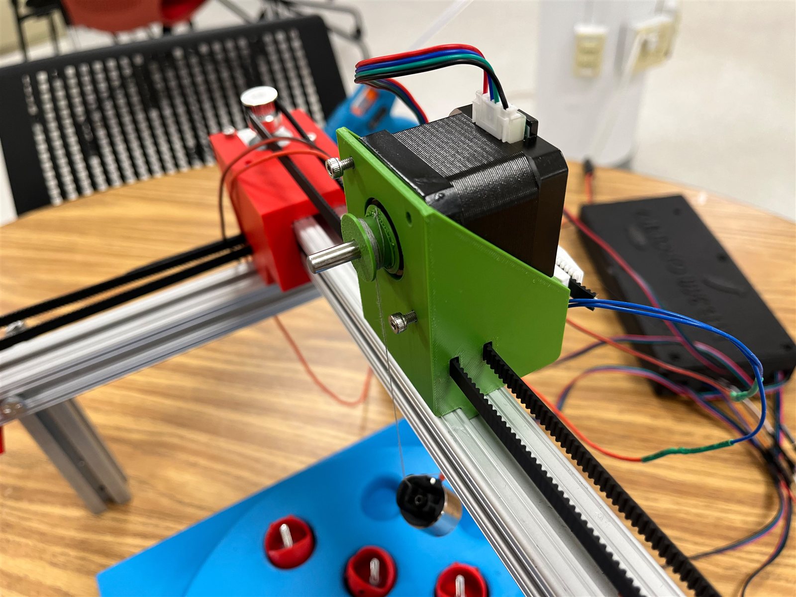
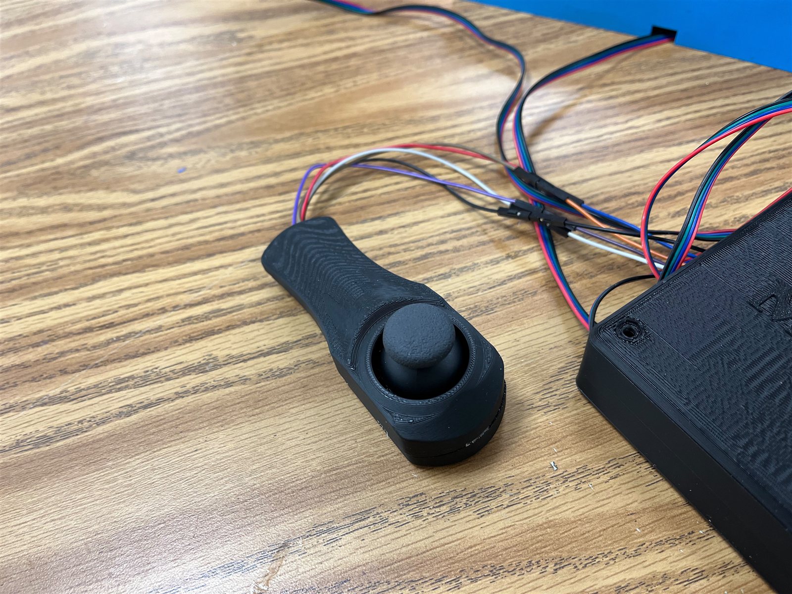
The magnetic end effector collects pieces by their steel pins. A short press on the joystick starts the dip sequence; a double press toggles the electromagnet.
Rotating game board
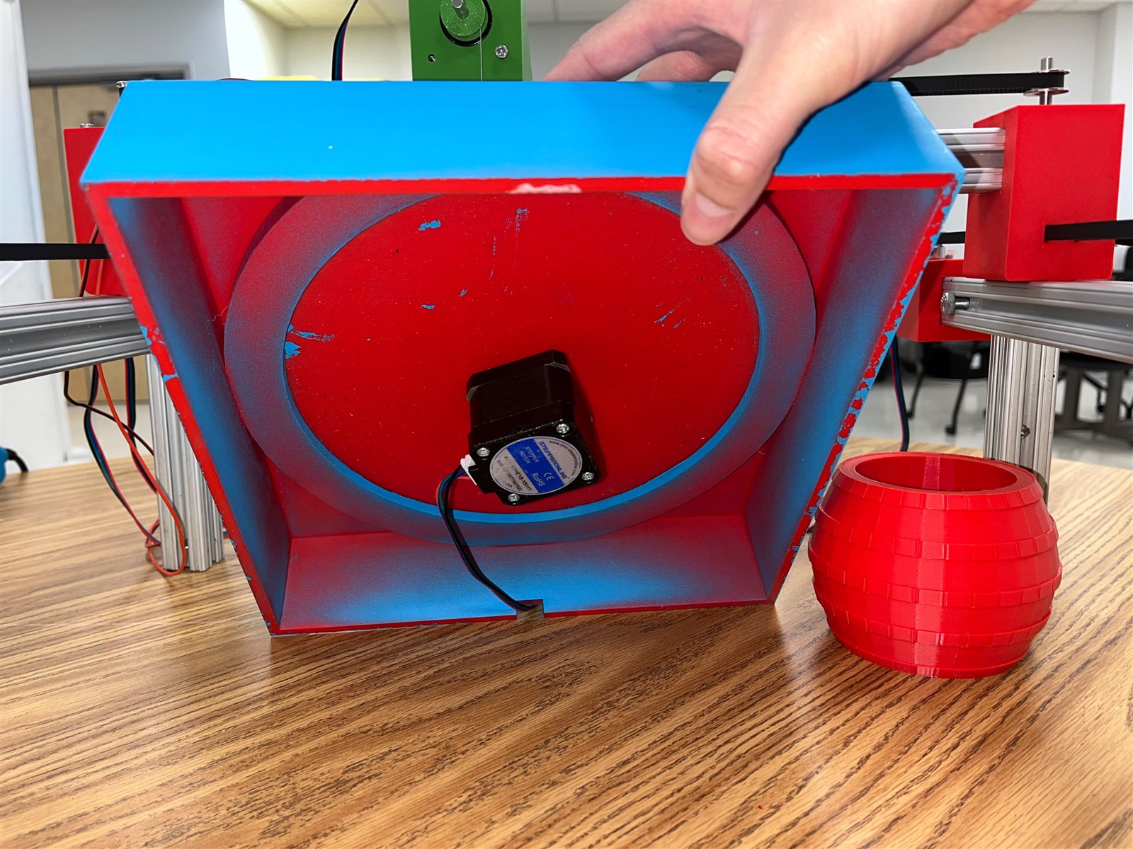
The blue printed enclosure contains a separately driven rotating plate. Its underside motor changes the target field while the player moves the gantry. The control sequence defines timed rounds, reverses direction between stages, and varies speed during the final round.
Controls and code
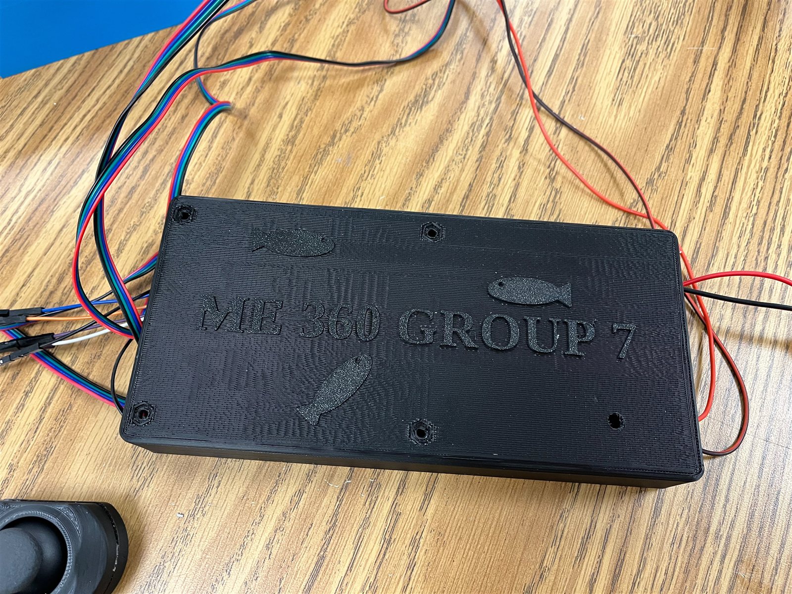
The final team-developed control sketch targets an MKS Base board with an ATmega2560; individual authorship is not established in the available evidence. It reads two joystick axes, calibrates their center at startup, applies a dead zone, ramps X-Y speed, and generates step pulses without blocking the timed board sequence. Button timing distinguishes the Z dip, magnet toggle, and game-round control. The three-round sequence changes the plate speed and direction, then introduces randomized timing and speed during the final round.
Download the team-developed control sketch.
During integration, the X control initially moved opposite the intended direction. The team corrected it with a software direction inversion before the final demonstration. The code assumes the gantry powers on with the joystick centered and the Z mechanism at its upper position. It tracks position from commanded steps and does not use end-stop or software travel-limit enforcement. The electromagnet remains energized until toggled off or the controller resets. The hardware must remain supervised while this sketch is running.
Prototype evidence
The available recording shows the magnetic fishing interaction: the end effector lowers, lifts a game piece, and releases it. It does not demonstrate the complete joystick-controlled X-Y-Z sequence or establish accuracy and repeatability.
Demonstration and limitations
The classroom demonstration completed successfully. Joystick-controlled X-Y motion, the automatic Z dip, electromagnet, rotating board, and all three software-controlled rounds worked together. The gantry covered the game-board area, visibly exceeding the minimum 2.5 × 2.5 in work area, but its X-Y bounds were not calibrated or measured.
Video of the final classroom demonstration is coming soon.
The final prototype has no physical indicator showing whether the electromagnet is energized. Its open-loop axes also lack homing and calibrated travel limits. These constraints, together with the deliberately slow Z motion, remain the main usability and control limitations.