Electromechanical prototyping · Completed
Cartesian pen plotter exercise
A two-axis pen plotter developed from a single linear-stage test into an assembled X-Y mechanism with motorized pen actuation.
Boston University · ME360 · Team exercise · Fall 2026
On this page
- Role
- Team member
- Contribution
- Built and tested as a team; I connected my computer to the motor controller and sent the test G-code through Repetier-Host.
- Evidence
- Produced recognizable square and circular traces; accuracy and repeatability were not measured
Objective
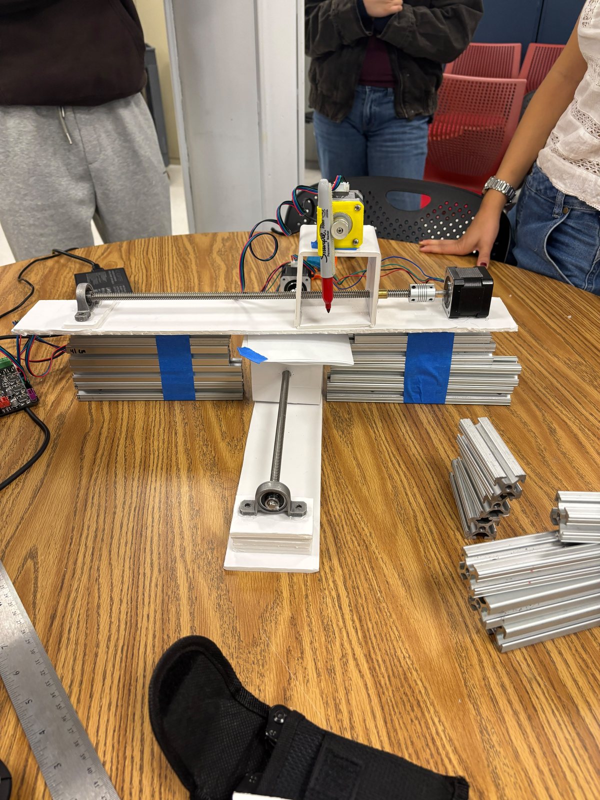
This in-class exercise established the basic mechanical and control sequence for Cartesian motion. The team first tested one linear axis, then crossed two stages, added a motorized pen lift, and commanded square and circular paths.
The exercise became an early motion study for the later 2.5-DOF fishing game, but the two systems use different mechanical layouts. This plotter used lead screws and temporary foam-board structure; the fishing game moved to belts, aluminum extrusion, and printed housings.
First linear stage
The first prototype isolated one axis so the motor, coupler, lead screw, bearing support, and carriage could be checked together. A rigid base located the motor and screw while a foam-board carriage translated along the axis.
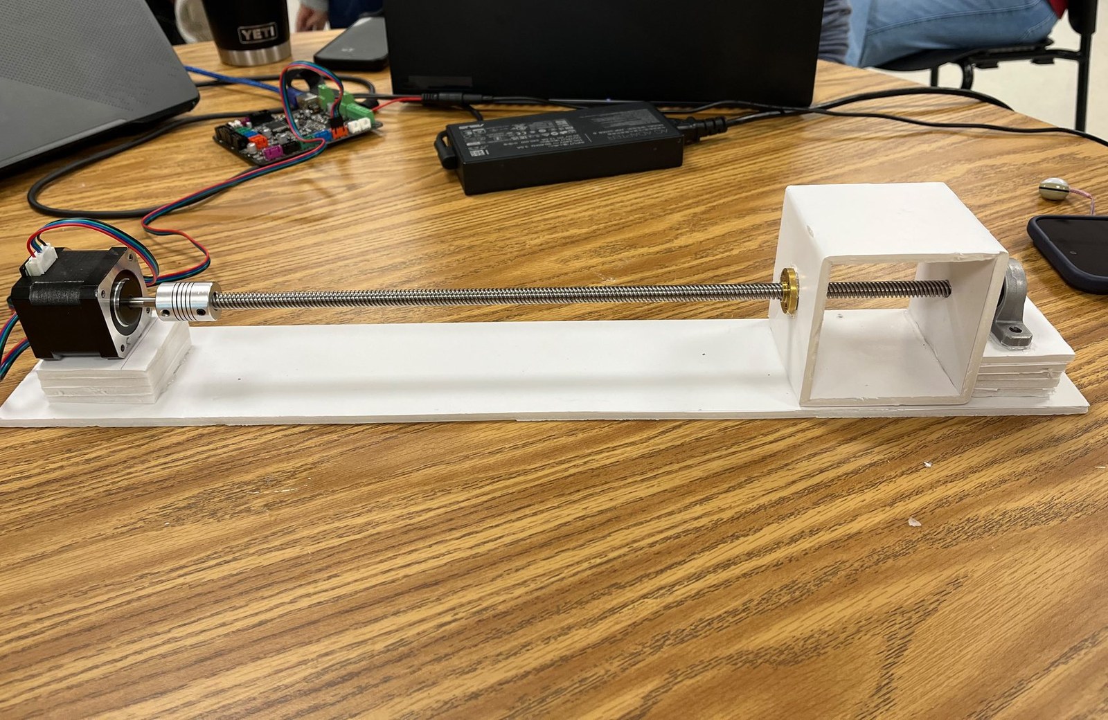
This stage reduced integration risk: the team could confirm rotation direction, travel, support alignment, and basic carriage movement before carrying the first stage on a second axis.
X-Y assembly
The next build mounted two lead-screw stages at right angles and added a motorized marker carriage. Foam board, tape, and simple brackets kept iteration fast. These parts were prototype tooling rather than the structure intended for the later course project.
Motion commands
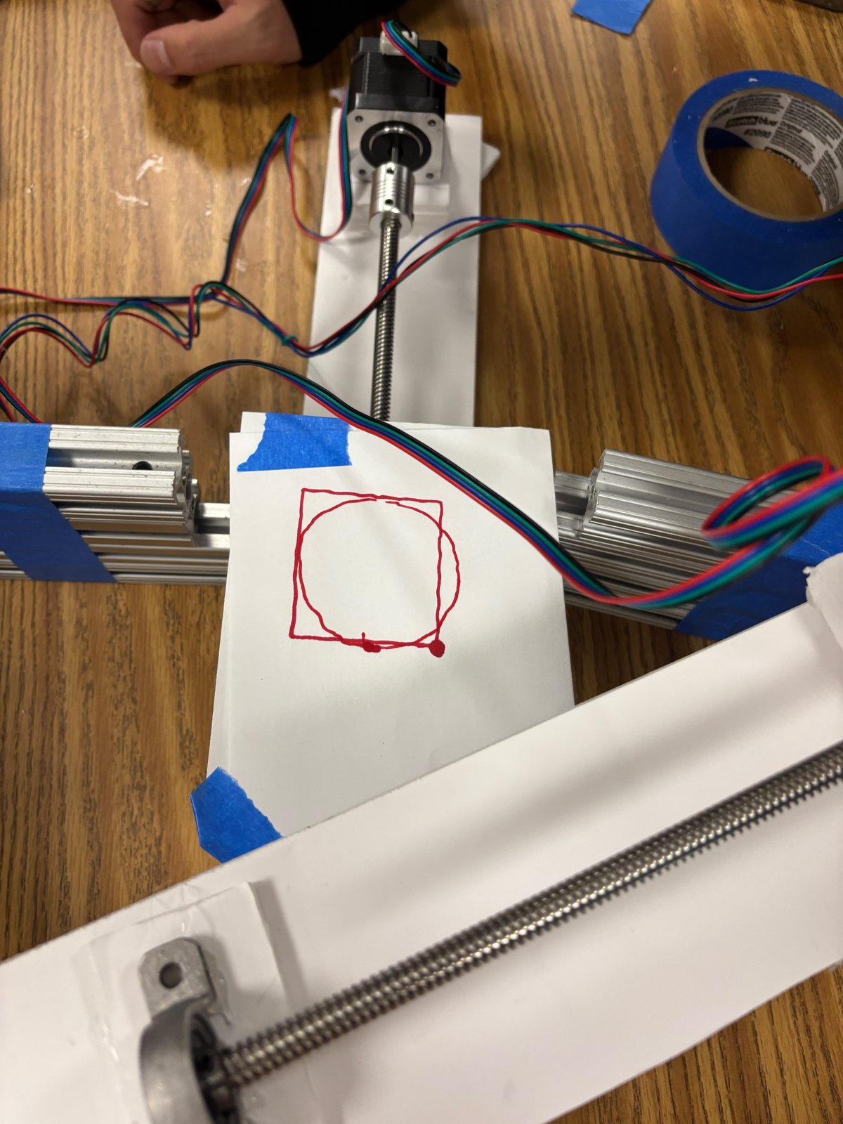
I connected my computer to the motor-control board and used Repetier-Host, a 3D-printer host application, to send the test G-code. Linear G1 moves traced a 50 × 50 mm square. A clockwise G02 move traced a 25 mm-radius circle. Extruder-axis commands raised and lowered the pen mechanism before and after each path.
Download the square path · Download the circle path
Path tests
The recordings show coordinated X-Y movement and pen actuation. They demonstrate functional motion, but they do not establish dimensional accuracy, backlash, or repeatability.
Result and limitations
The exercise progressed from a working single axis to coordinated two-axis paths with pen actuation. Rounded corners and line waviness remained visible. No calibrated measurements are available for commanded versus actual dimensions, backlash, repeatability, or stage speed, so the result is limited to a functional demonstration.
This was a rapid in-class build, and no CAD model was produced.