BU Rocket Propulsion Group · Completed
Converging-diverging rocket nozzle
A small rocket nozzle developed from compressible-flow calculations through CAD, pressure analysis, fabrication, and static-fire integration.
BU Rocket Propulsion Group · Hybrid Intro Project · Project Engineer · Fall 2024
Objective
I completed the Hybrid Intro Project with the Boston University Rocket Propulsion Group (BURPG). New members design, manufacture, and static-fire a small rocket nozzle while learning the group’s design-review process.
I led the mechanical work. Using Rocket Propulsion Elements as my main reference, I calculated the nozzle performance and geometry, created the part and assembly CAD, produced the drawings, ran the pressure FEA, and planned the resin-printing process. I delivered that work through conceptual, preliminary, and critical design reviews, then helped integrate the nozzle with the team’s electrical control and data-acquisition system.
Approach
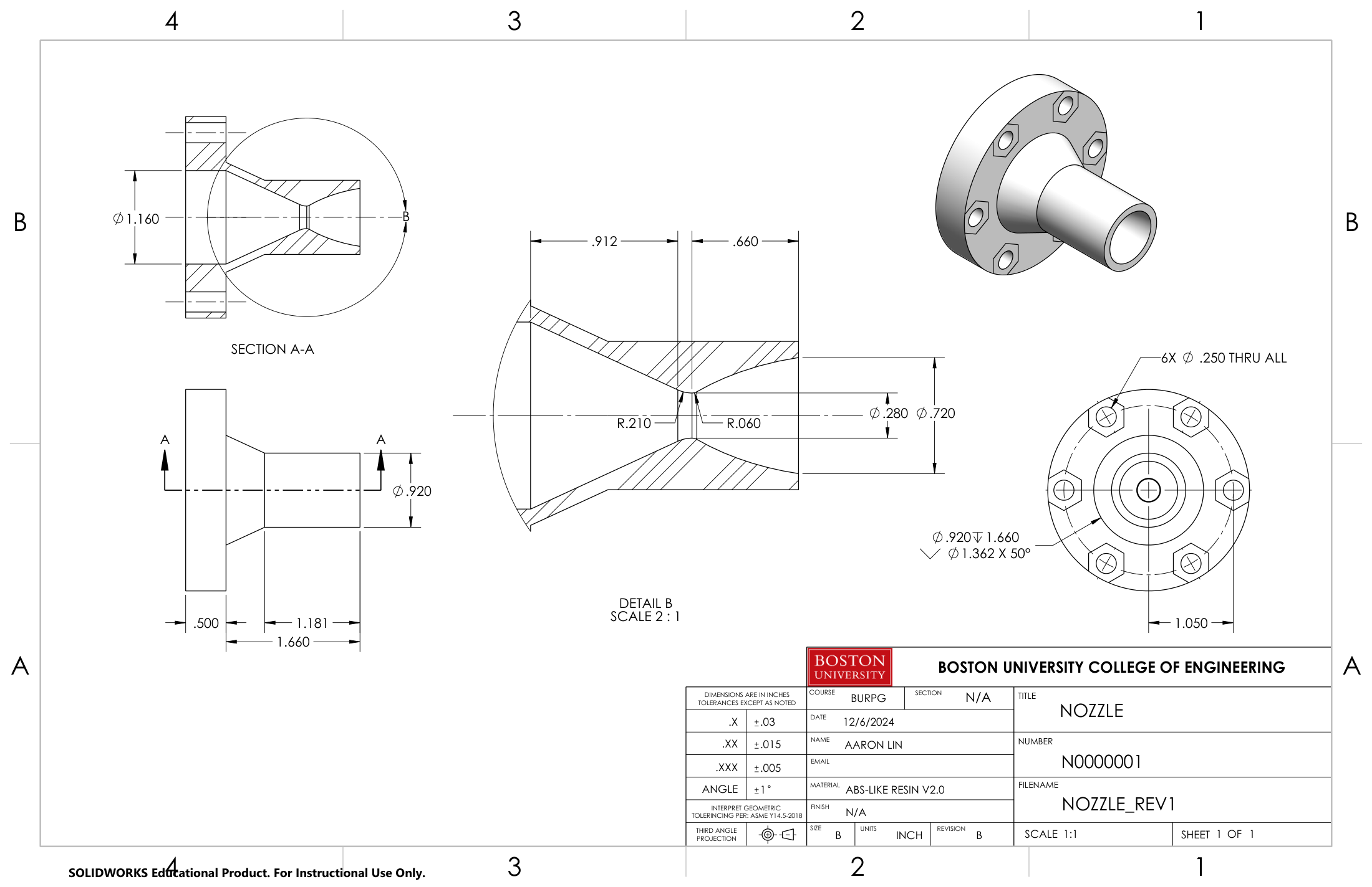
The starting requirements were an 80 psi chamber pressure, 3250 K chamber temperature, 13 g/s mass flow, and a 2.1 psia target exit pressure corresponding to approximately 45,000 ft. The full assembly also had to stay within a 1.05 in maximum diameter.
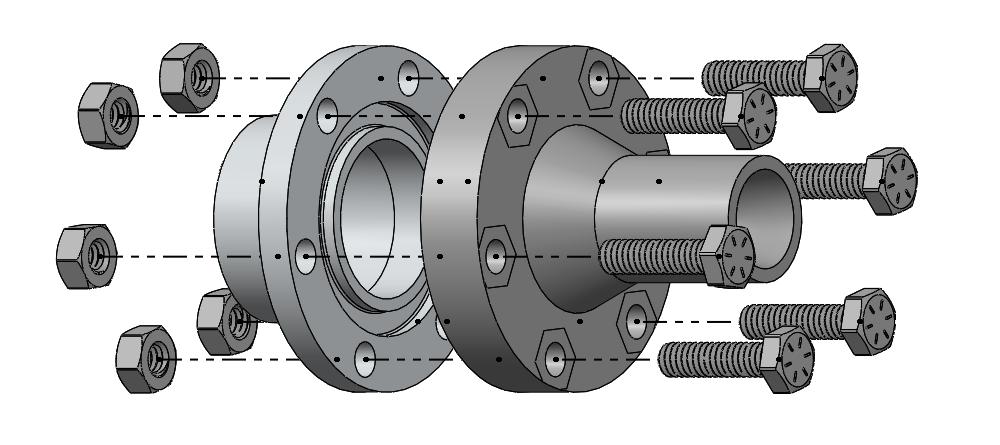
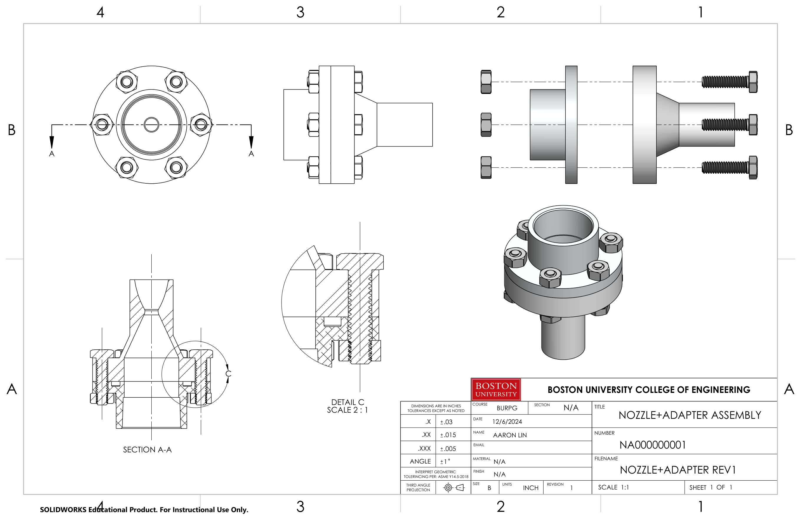
I used one-dimensional isentropic-flow relations to size the throat and exit. The final design had an exit-to-throat area ratio of 6.521. I then modeled the nozzle and a six-bolt adapter that connected it to the team’s 1-inch NPT chamber.
We chose resin printing because it could produce the internal geometry within the project schedule. The material’s temperature sensitivity meant that the structural simulation could only address the pressure load.
Analysis
| Quantity | Design-review value | Use in the model |
|---|---|---|
| Chamber pressure | 80 psi | Applied chamber load |
| Throat pressure | Approximately 46.3 psi | Applied throat load |
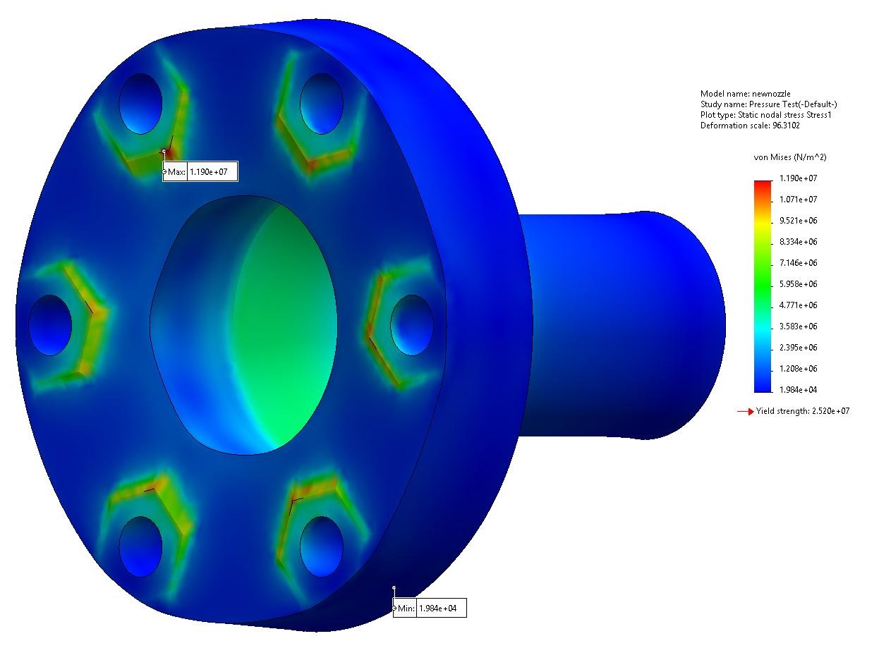
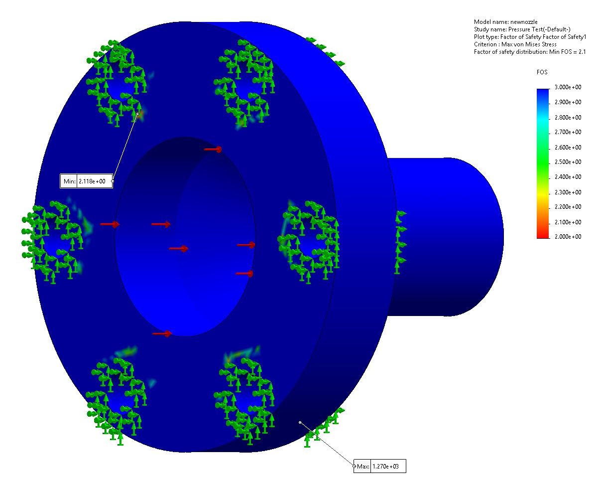
| Maximum von Mises stress | 11.90 MPa | Computed stress in the pressure model |
| Assumed yield strength | 25.20 MPa | Estimated as 70% of resin tensile strength |
| Minimum factor of safety | 2.12 | Result under those material and boundary assumptions |
The pressure-only model produced a minimum factor of safety of 2.12. Before using that result to predict hot-fire performance, I would add temperature-dependent resin properties and heat transfer to the analysis.
Build and test
I printed the nozzle, integrated it with the chamber and seals, and helped assemble the relay ignition circuit for the static fire.
This project took the nozzle from compressible-flow calculations to a manufactured part integrated into a static fire. The pressure model supported the design review and fabrication decision; the hot-fire recording demonstrated system integration rather than quantified nozzle performance. For a second iteration, I would pair a mesh-converged thermal-structural model with chamber-pressure measurements, wall-temperature data, and a documented post-fire inspection so the analysis could be compared directly with the test.