CAD coursework · Completed
SolidWorks modeling exercises
SolidWorks parts and assemblies recreated from instructor-provided engineering drawings.
Boston University · ME357 · Individual coursework · Spring 2025
On this page
- Role
- Individual CAD coursework
- Contribution
- Recreated instructor-specified geometry and produced assemblies and drawing views.
- Evidence
- Scope: parts, assemblies, section views, exploded views, drawings, and BOMs
Scope
This collection includes in-class exercises and homework from ME357. I recreated mechanical parts and assemblies in SolidWorks from instructor-provided engineering drawings. The models and drawings demonstrate CAD fluency; the underlying designs were supplied by the course.
The course work included:
- parametric part models built from dimensioned drawings;
- assemblies with standard fasteners and purchased components;
- section and exploded views;
- drawing sheets with dimensions and bills of materials; and
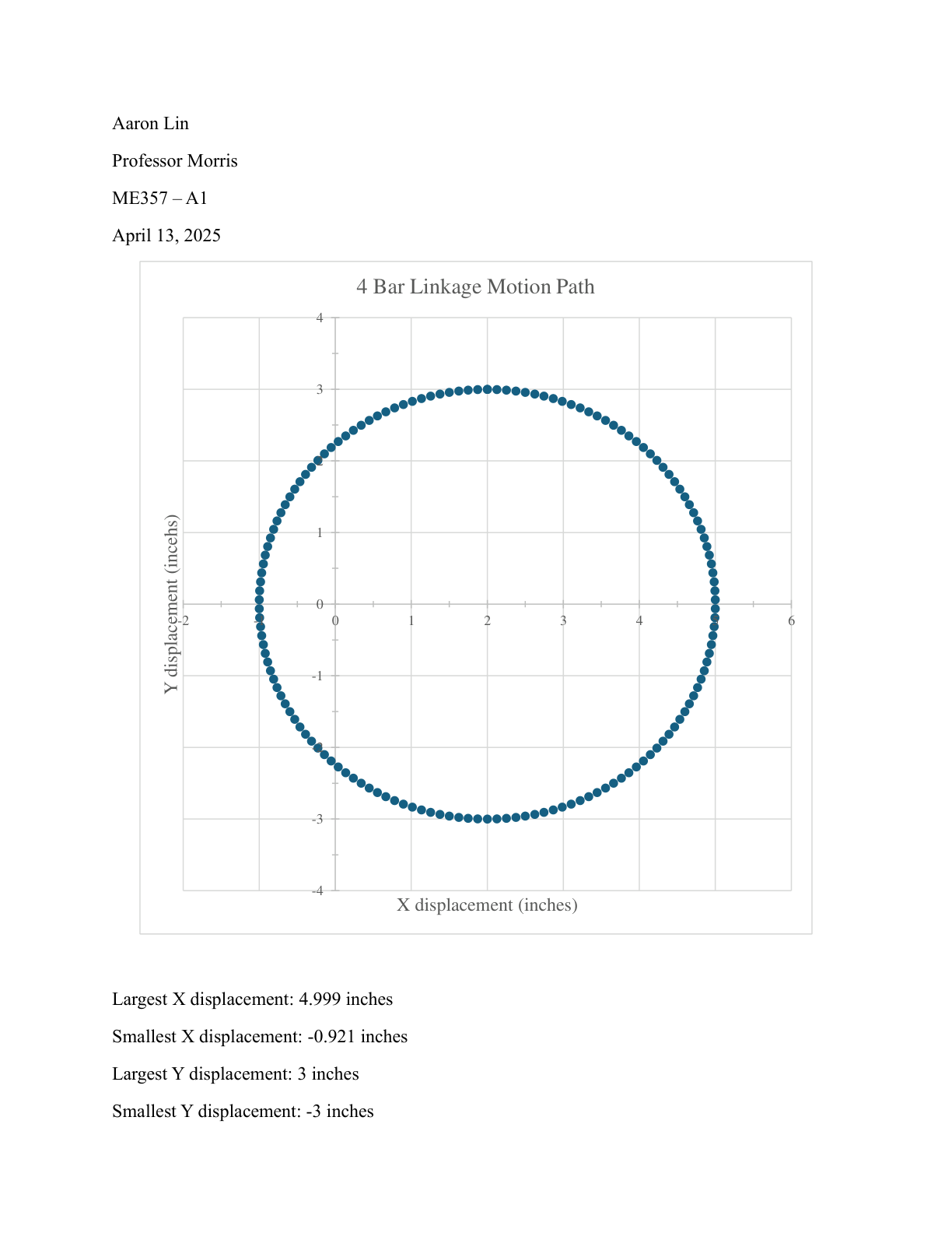
- basic motion studies for mechanisms and assemblies.
Modeling workflow
Each exercise began with a supplied drawing rather than an existing CAD file. I translated the views and dimensions into a feature order, constrained the base sketches, and built repeated or symmetric geometry with patterns and mirrors where the drawing supported them. The final models had to agree with the drawing while remaining readable in the feature tree.
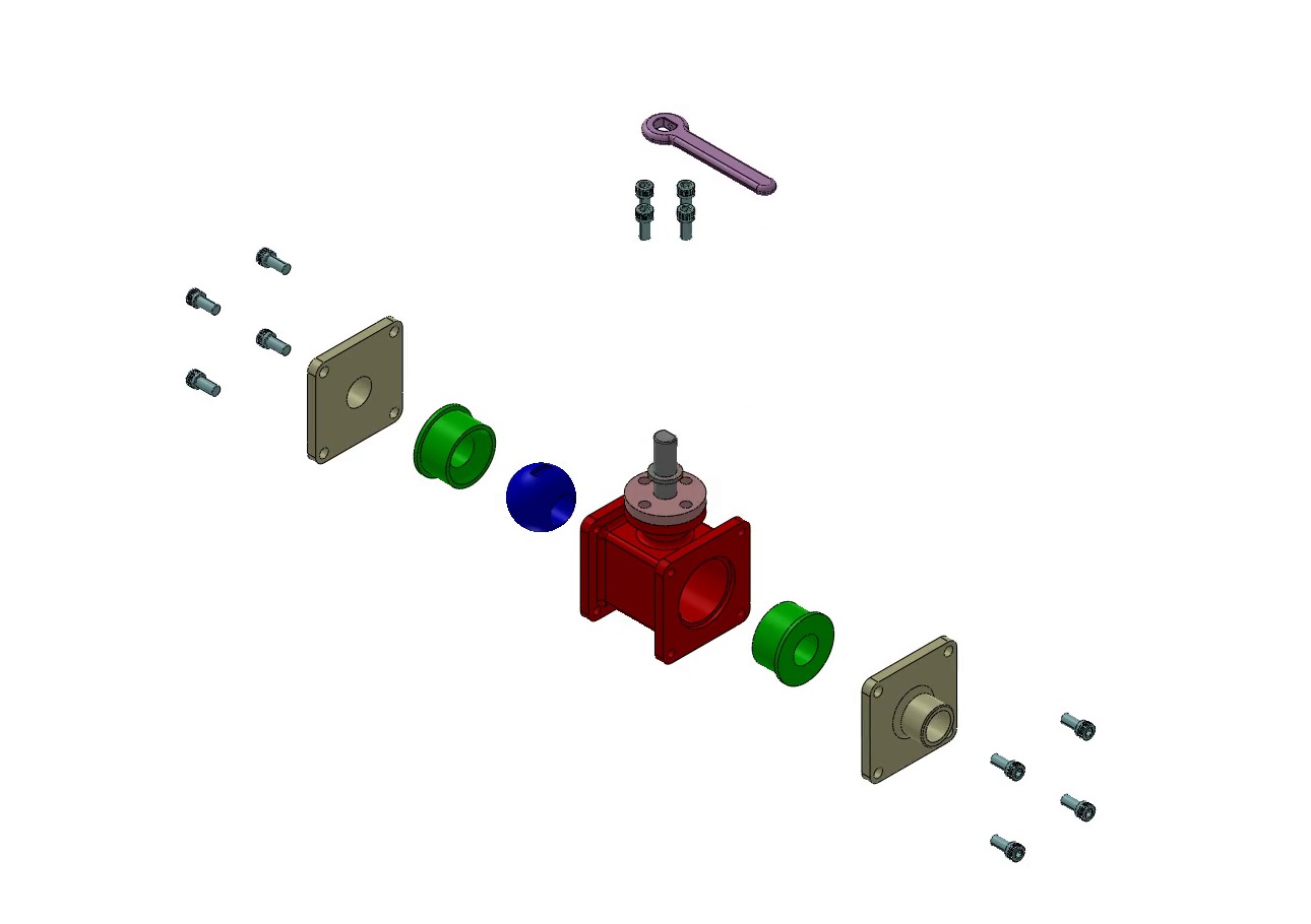
For assemblies, I inserted standard hardware and applied mates that reproduced the intended motion or fixed relationship. Section and exploded views then served different checks: a section exposed the internal interfaces, while an exploded view showed how parts and fasteners fit together without hiding them inside the housing.
Ball valve assembly
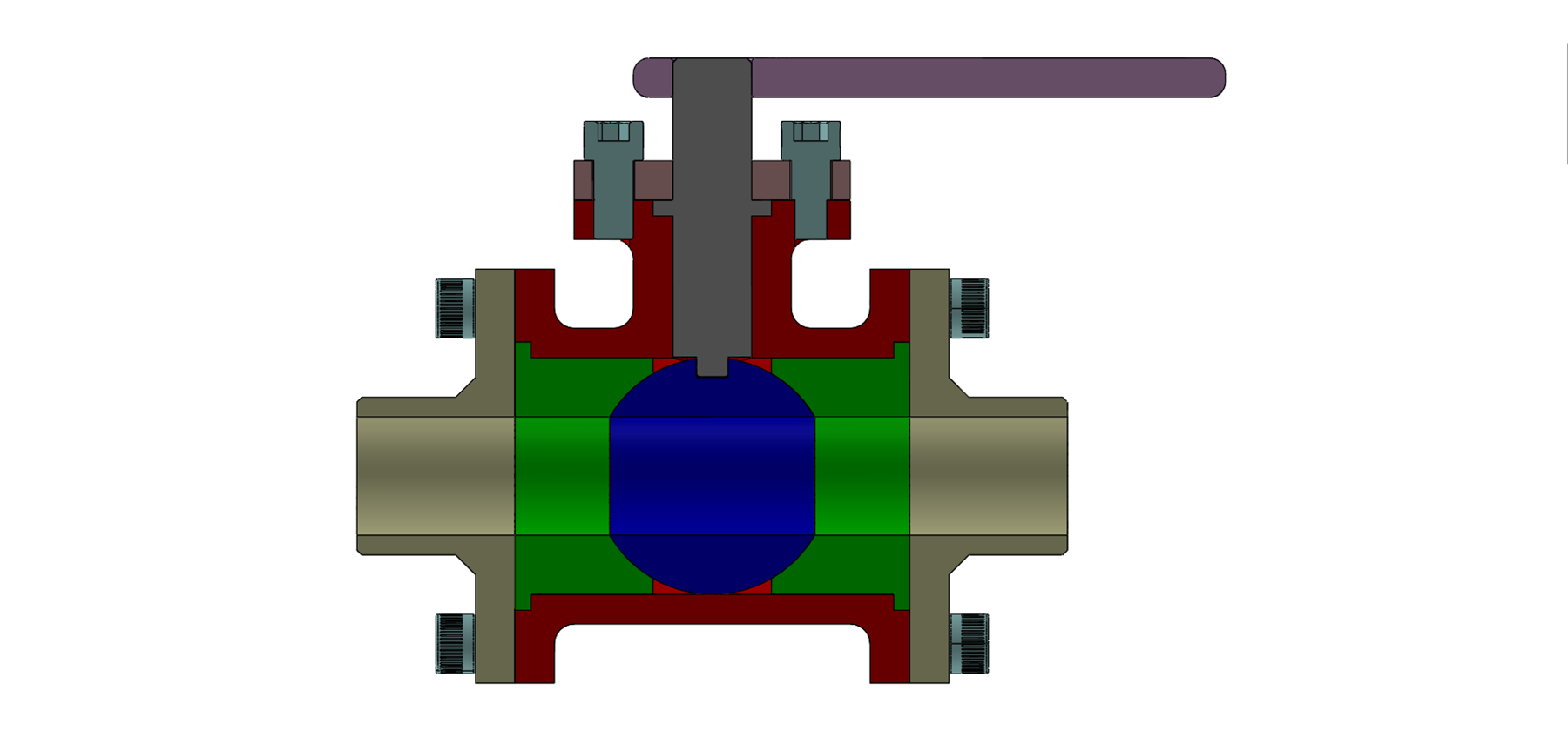
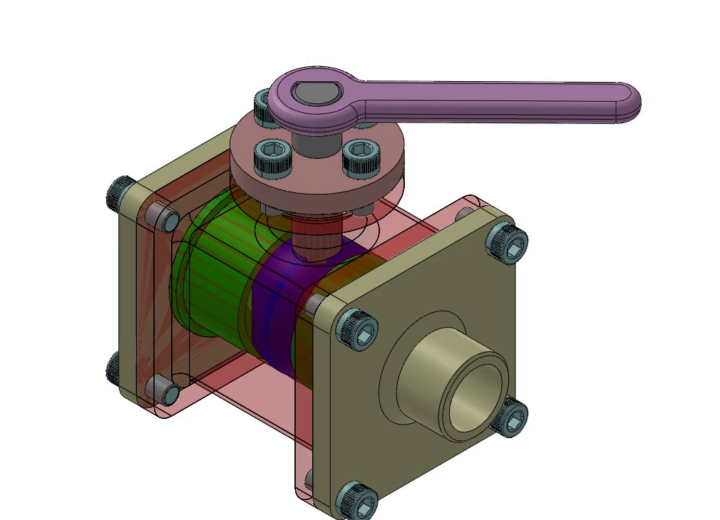
The ball valve exercise combined a housing, ball, shaft, covers, handle, reducers, and fasteners. I assembled the supplied geometry, checked the internal arrangement with section views, and created exploded and motion views.
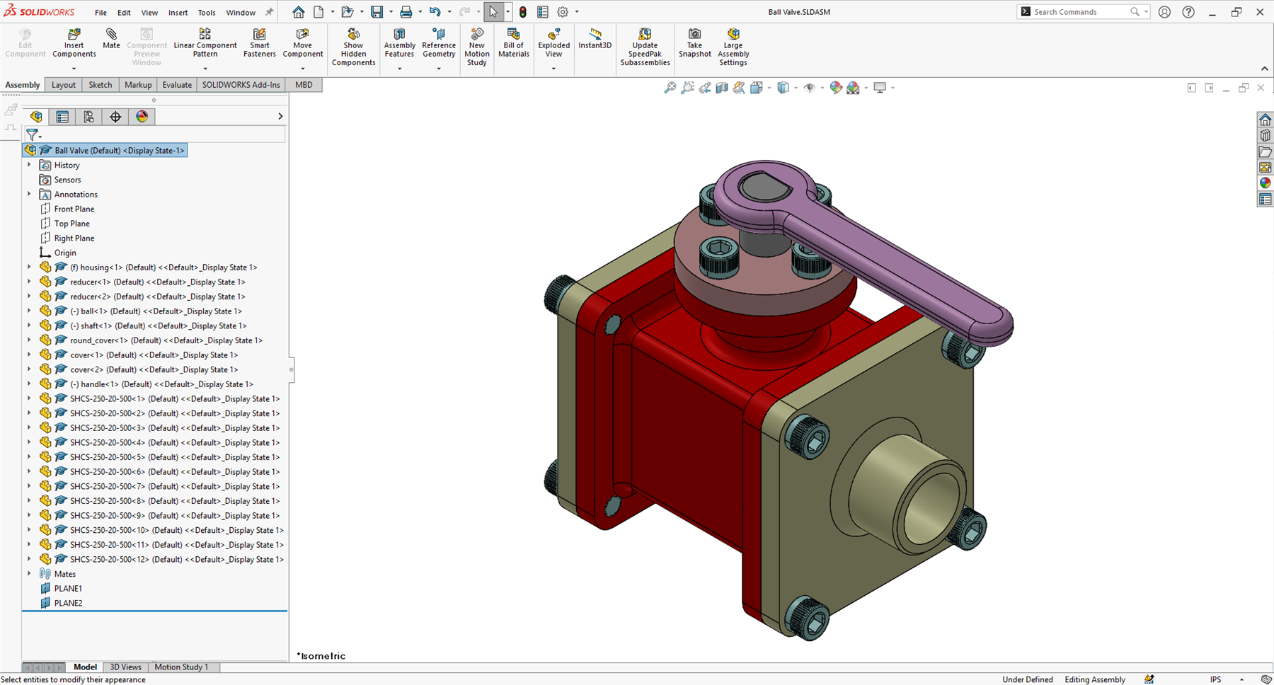
The section view made the stack of the ball, shaft, housing, covers, and fasteners legible in one frame. The exterior view then confirmed the handle position and the relationship between the two reducers and the main body. Together, the views document both the assembled form and the internal arrangement.
Wheel assembly and bill of materials
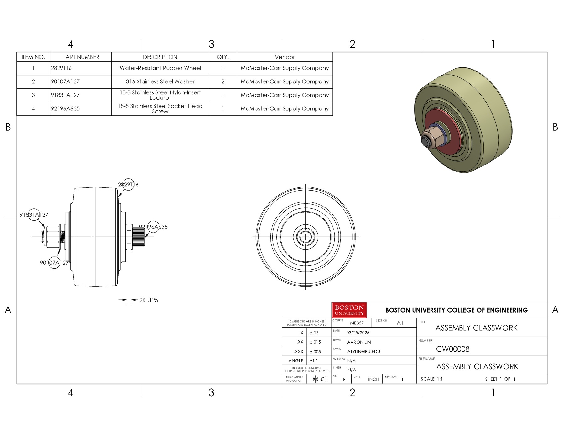
The wheel exercise combined a purchased rubber wheel with a screw, washers, and a locknut. The drawing identifies the components in a bill of materials and shows their assembled arrangement.
Linkage assemblies
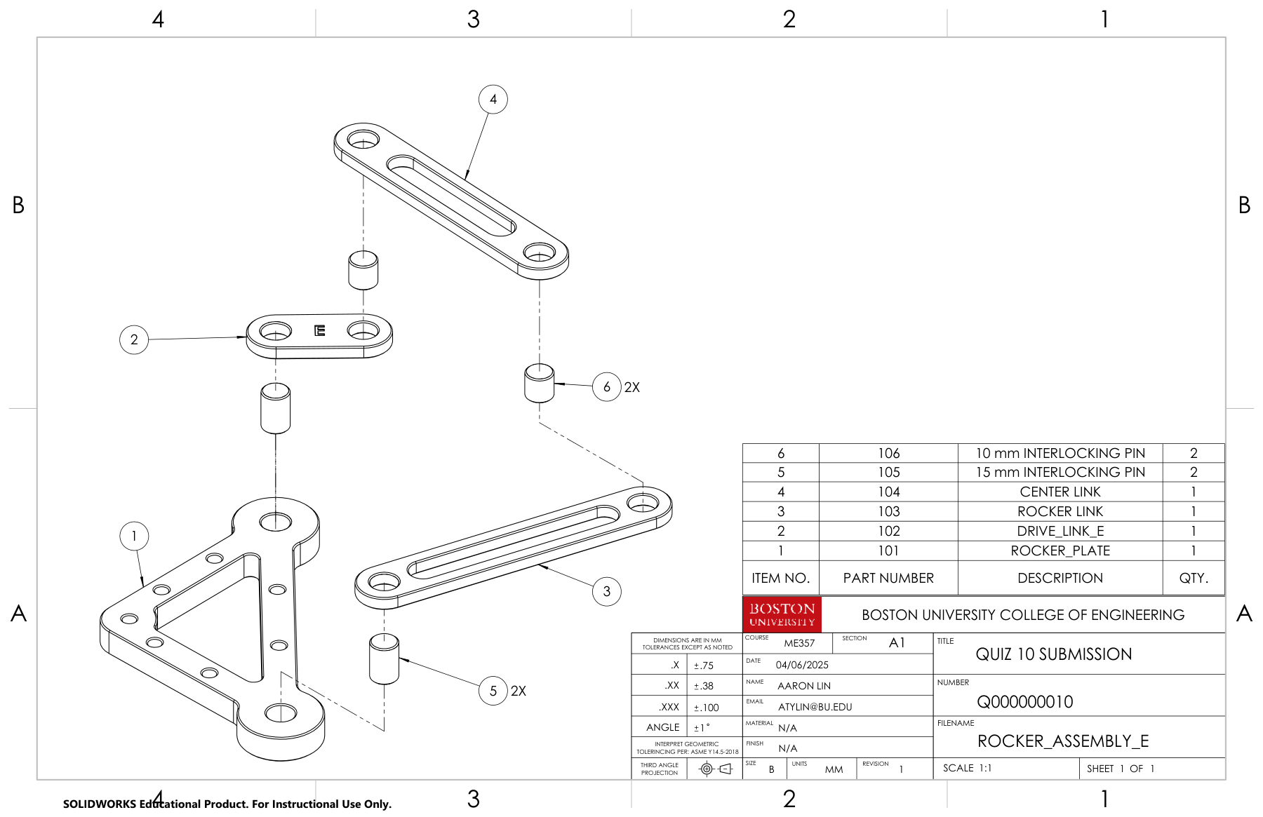
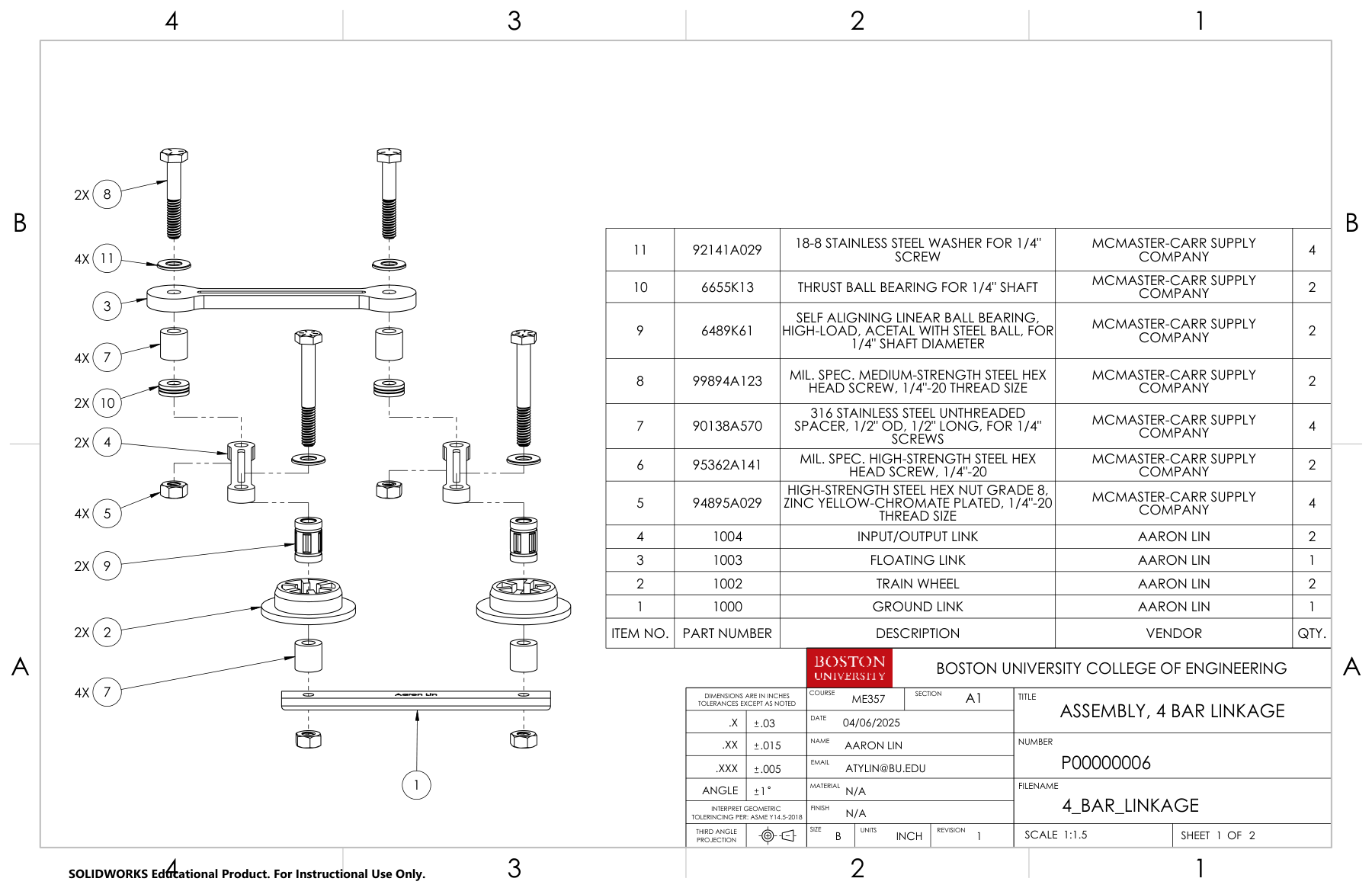
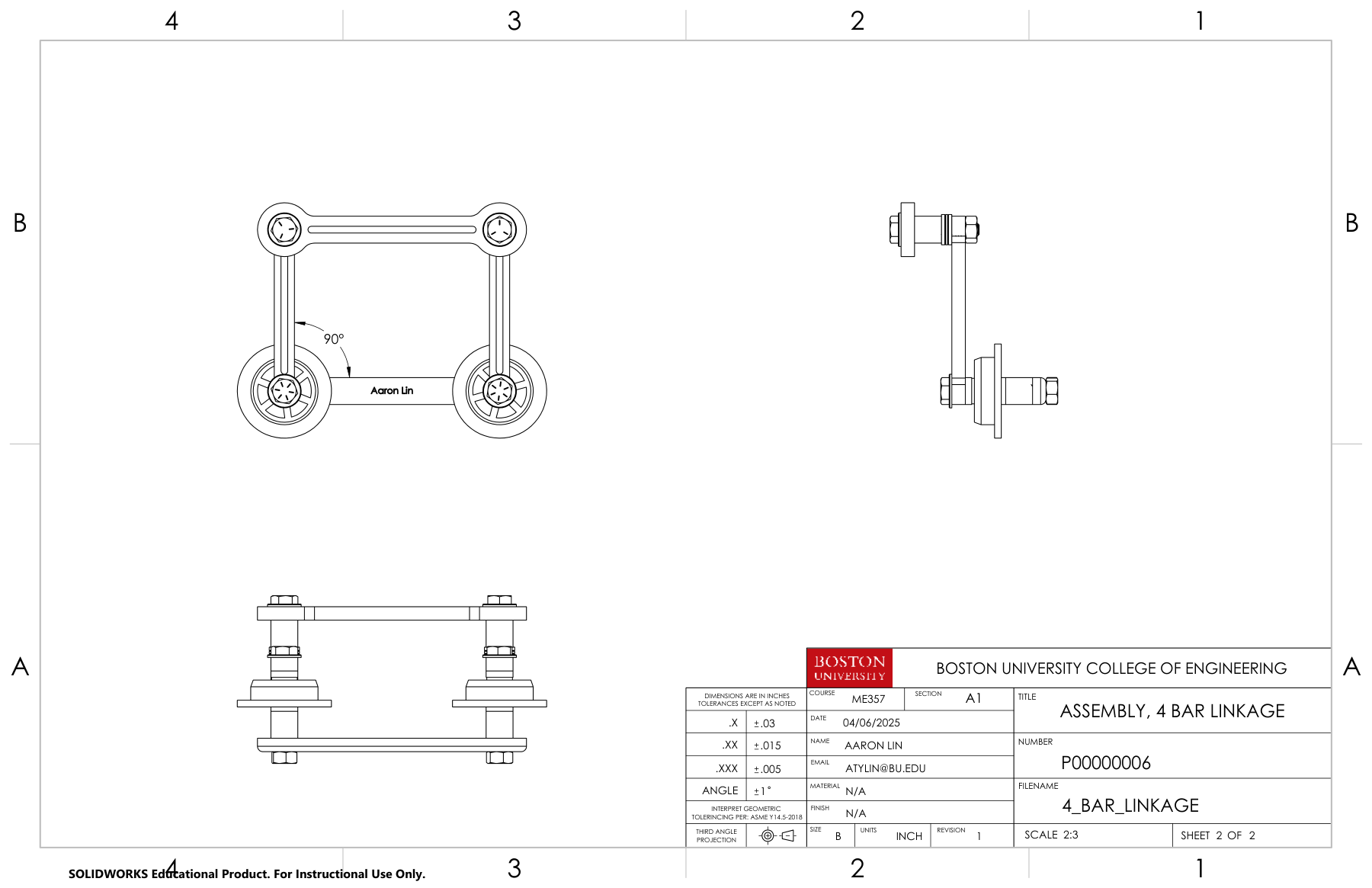
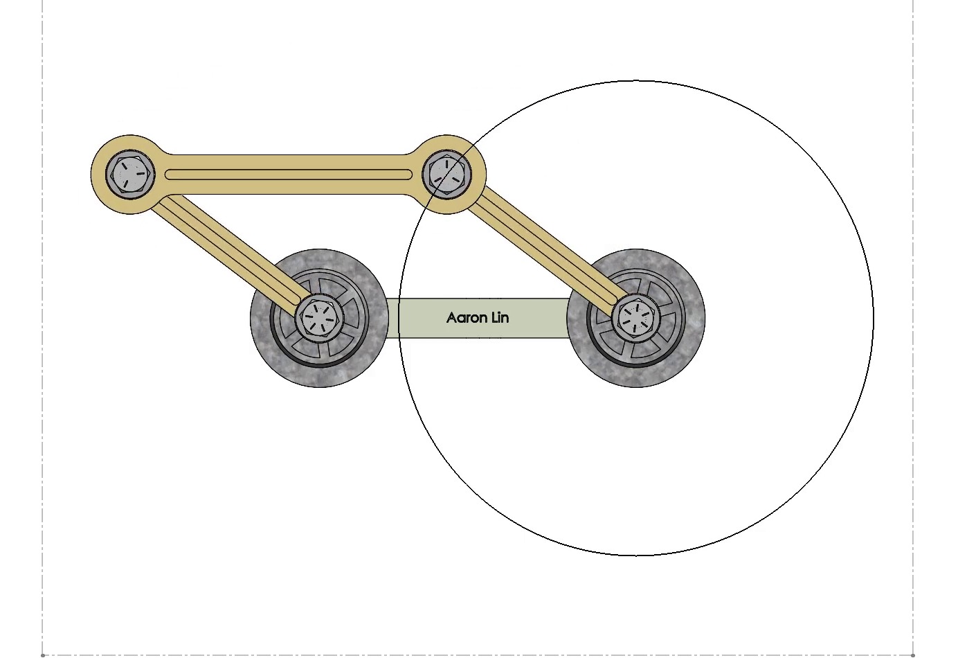
The rocker and four-bar exercises used exploded views to show links, pins, bearings, and fasteners. The assembled four-bar drawing shows the relationship between the links and their supports.
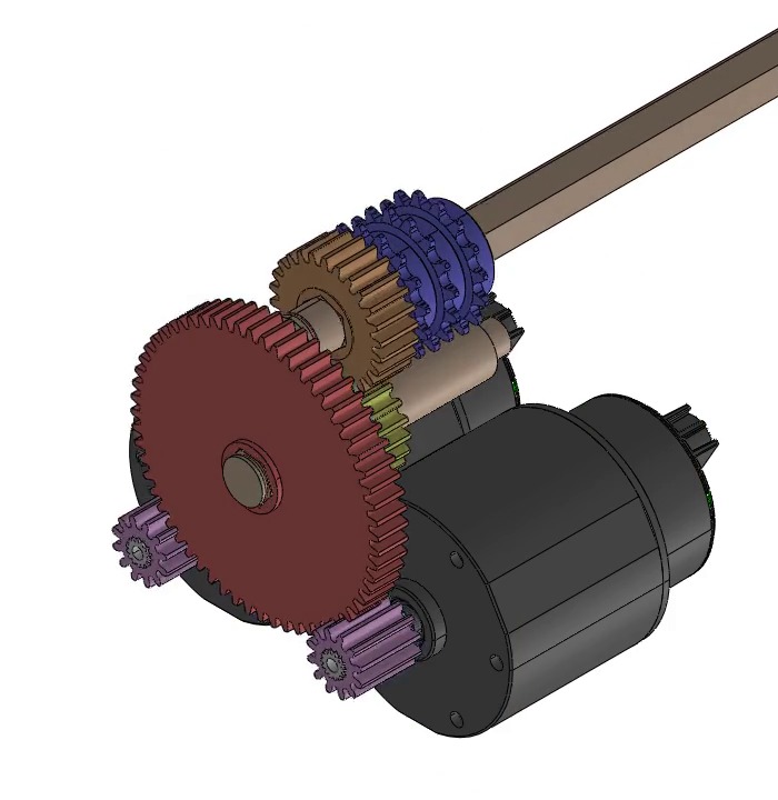
Gearbox assembly
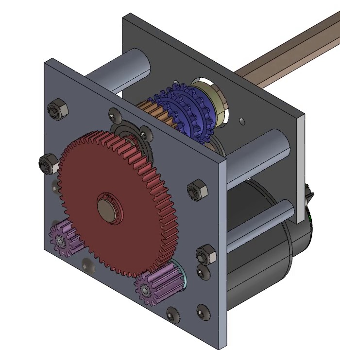
The gearbox coursework used supplied components. These stills from the assembly animation show the supporting plates and the gear arrangement with the plates hidden.
Part models and drawings
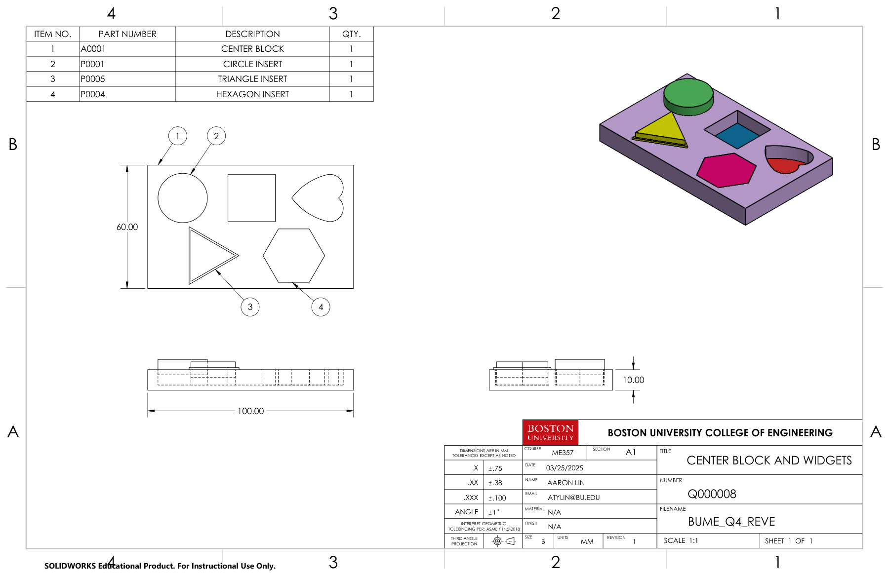
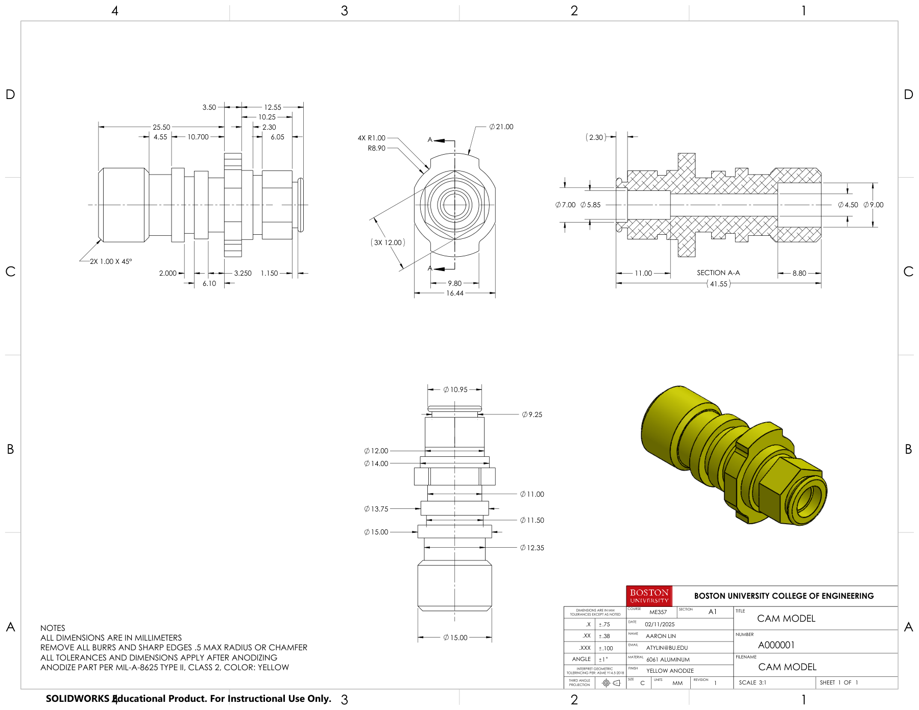
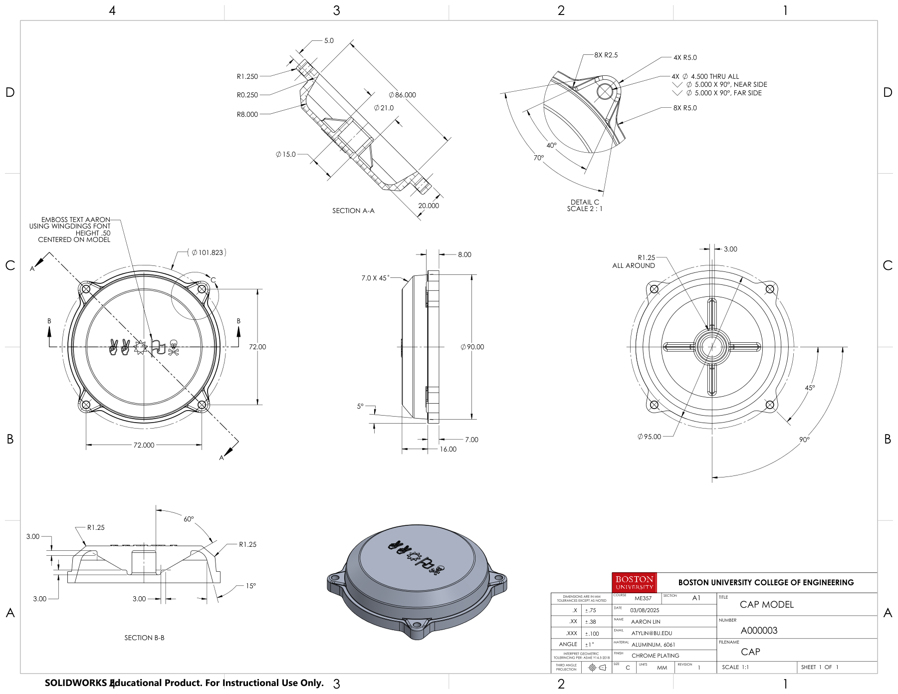
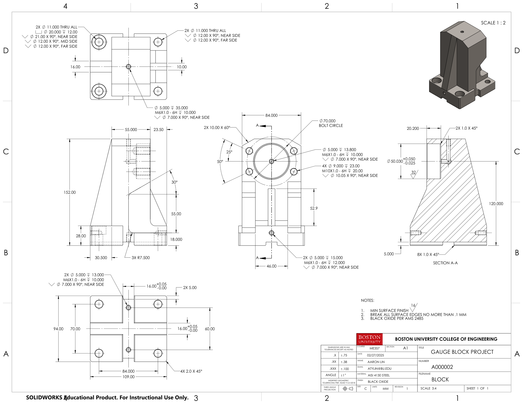
These drawings pair modeled geometry with dimensions, sections, and detail views. Each part follows an instructor-provided exercise; the images document my modeling and drawing work.
Insert assembly