Structural design · Completed
Acrylic truss design and test
A team truss project developed through statics, buckling analysis, MATLAB iteration, fabrication, and load testing.
Boston University · EK301 · Team of three · Fall 2025
On this page
- Role
- Team member
- Contribution
- Truss analysis, report preparation, construction, and testing as part of a three-person team.
- Evidence
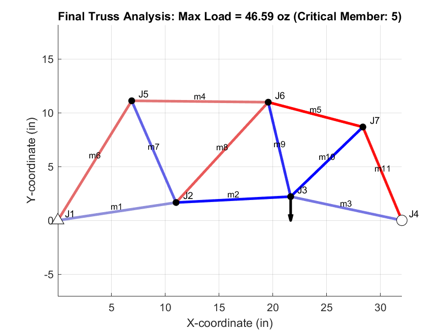
- Final MATLAB prediction: 46.59 oz; physical build met the 16 oz minimum
Objective
Our three-person team designed an acrylic truss, analyzed its member forces and buckling limits, built it, and tested it under load. We used the analytical model to compare geometries before committing material to the final structure.
The course constraints required a statically determinate truss with a 32 in support span, members between 8.5 and 14 in, no crossed members, and no more than 120 in of total member length. The target was to carry a 32 oz live load for at least one minute while keeping material cost low.
Analysis
We represented the truss with a connection matrix and solved the joint-equilibrium equations in MATLAB. Compression members were checked against an experimentally fitted buckling relation, while tension members were checked against the material limit used in the course model.
The script took joint coordinates, member connectivity, support directions, and the load location as inputs. It assembled the x- and y-equilibrium equations, solved member-force ratios for a one-ounce reference load, and then scaled those ratios to the first predicted member failure. A course buckling fit of the form Fcrit = C L^-α ± Ufit supplied the compression limit, with C = 1909.7 oz, α = 1.74, and Ufit = 1.58 oz.
The preliminary report compared two designs:
| Candidate | Predicted maximum load | Estimated cost | Load-to-cost ratio | Predicted critical member |
|---|---|---|---|---|
| Design 1 | 42.95 ± 1.58 oz | $183 | 0.2345 oz/$ | Member 4 |
| Design 2 | 44.93 ± 1.58 oz | $190 | 0.2368 oz/$ | Member 4 |
We selected Design 2 because it had the higher predicted capacity and slightly better load-to-cost ratio. A later final-model plot predicted 46.59 oz and identified member 5 as critical after the geometry was updated.
Model checks
We checked the MATLAB member forces against a hand-solved practice truss and an external two-dimensional truss solver. The two preliminary candidates also passed the geometric checks in the project manual. Those checks reduced the chance of a matrix-assembly error, but they did not validate the acrylic buckling fit or represent joint flexibility.
Build and test
We built and load-tested the final truss. It met the course’s 16 oz minimum load requirement, but we did not retain a photograph or measured test record. The modeled values above are documented predictions; the physical result is limited to my recollection that the structure passed the minimum.
The pin-jointed model assumed ideal geometry and connections. It did not represent joint alignment, adhesive quality, or construction variation, all of which could reduce the capacity of the built truss.
The model also treated each member as carrying pure axial load. Small offsets at the joints, uneven adhesive thickness, or out-of-plane bowing would add bending that the equilibrium solution cannot see.
My contribution
I worked as one of three team members on the analysis, report, construction, and test. The surviving documentation records the work as a team submission rather than assigning each calculation or fabrication step to one person.