Electronics prototype · Completed
Room temperature monitor
A compact Arduino temperature monitor with a display, threshold alerts, and an enclosed electronics assembly.
Boston University · EK131 · Spring 2025
On this page
- Role
- Individual course project
- Contribution
- Firmware, electronics assembly, and enclosure packaging.
- Evidence
- Displays °C/°F and alerts outside 60–75°F
Objective
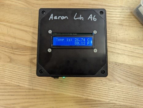
I built and programmed an Arduino Uno temperature monitor with a TMP36 sensor, 16×2 LCD, red and green LEDs, and a buzzer. It displays Celsius and Fahrenheit and alerts the user when the temperature moves outside 60–75°F.
I wrote the firmware, assembled the circuit, arranged the components inside an ABS enclosure, and documented the build in a technical report.
Signal path and controls
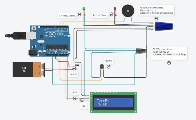
The Arduino reads the TMP36’s analog voltage, converts that value to Celsius, calculates Fahrenheit, and updates both values on the LCD. The firmware then compares the Fahrenheit reading with the two thresholds. A reading inside the range leaves the green indicator on; a reading below 60°F or above 75°F switches to the red indicator and sounds the buzzer.
I used an I²C display to reduce the number of signal wires between the screen and the Arduino. A two-position switch disconnects the 9 V battery, while the Arduino’s regulated 5 V rail supplies the sensor, display, LEDs, and buzzer.
Build
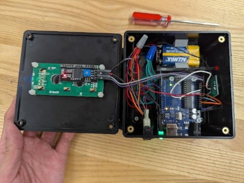
I used Arduino header connections and shared power and ground rails so the components could be reused. I arranged the display, sensor, switch, and alerts around a compact ABS enclosure and documented the LED resistor selection in the report.
The red LED uses a 220 Ω series resistor and the green LED uses 1 kΩ. Based on the component voltage drops recorded in the report, the corresponding currents were 13.6 mA and 2.8 mA. The larger resistor kept the green indicator within its intended operating range while reducing its share of the battery load.
Test / Results
- Power: The circuit drew 76 mA. A 690 mAh battery gives an ideal estimate of about nine hours, though the Arduino would shut down before the battery was fully discharged.
- Accuracy: The TMP36 datasheet lists ±1°C accuracy at 25°C. I did not calibrate the assembled monitor against a reference thermometer.
- Functional check: The display updated in both units and the red LED and buzzer activated outside the programmed range.
What I would change
The prototype proved the sensing and alert sequence, but it did not establish calibrated accuracy or real battery endurance. A second build would log the TMP36 reading beside a reference thermometer, test both threshold crossings, and measure runtime until the Arduino shuts down. I would also separate the sensor from the heat produced inside the enclosure and replace the loose internal wiring with retained connectors and shorter runs.